
Configuration Variables (CVs)
For Digital Command Control
The NMRA Standard provides a map and descriptions for Digital Decoder Configuration Variables. Configuration Variables allow the decoder to be customised for each locomotive or other mobile or stationary devices. Unless otherwise specified configuration Variables shall be stored in non-volatile memory and must not change when power is removed from the decoder over long extended periods of time.
Table 1 Multi-function Decoder Configuration Variables
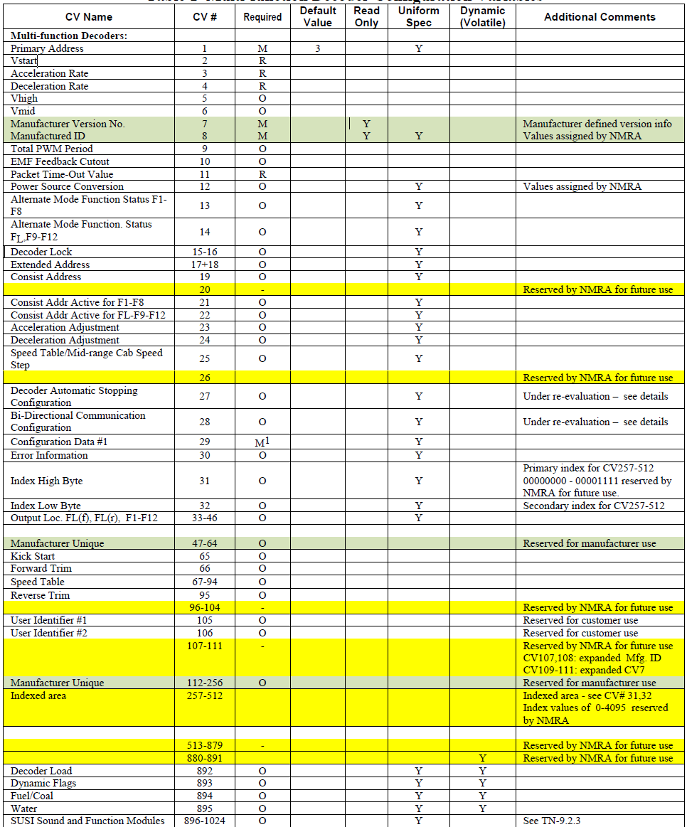
General Definitions
Binary numerical quantities are stored such that the rightmost bit is the least significant, and the leftmost is the most significant.
Configuration Variable MSB |d07|d06|d05|d04|d03|d02|d01|d00| LSB
Descriptions of Configuration Variables for Multi-Function Decoders
Configuration Variable 1 Primary Address
Bits 0-6 contain an address with a value between 1 and 127. Bit seven must have a value of "0". If the value of Configuration Variable 1 is "00000000" then the decoder will go out of NMRA digital mode and convert to the alternate power source as defined by Configuration Variable 12. This setting will not affect the Digital Decoder's ability to respond to service mode packets. The default value for this Configuration
Variable is 3, if the decoder is not installed in a locomotive or other unit when shipped from the manufacturer.
Configuration Variable 2 Vstart
Vstart is used to define the voltage drive level used as the start voltage on the motor. The voltage drive levels shall correspond linearly to the voltage applied to the motor at speed step one, as a fraction of available rectified supply voltage. When the voltage drive level is equal to zero, there shall be zero voltage applied to the motor. When it is at maximum "11111111", the full available rectified voltage shall be applied.
Configuration Variable 3 Acceleration Rate
Determines the decoder's acceleration rate. The formula for the acceleration rate shall be equal to (the contents of CV3*.896)/(number of speed steps in use). For example, if the contents of CV3 =2, then the acceleration is 0.064 sec/step for a decoder currently using 28 speed steps. If the content of this parameter equals "0" then there is no programmed momentum during acceleration.
Configuration Variable 4 Deceleration Rate
Determines a decoders braking rate, in the same fashion as acceleration above (CV3).
Configuration Variable 5 Vhigh
Vhigh is used to specify the motor voltage drive levels at the maximum speed step. This value shall be specified as a fraction of available rectified supply voltage. When the contents of CV5 equal "11111111", the full available rectified voltage shall be applied. Values of "00000000" or "00000001" shall indicate that Vhigh is not used in the calculation of the speed table.
Configuration Variable 6 Vmid
Vmid specifies the voltage drive level at the middle speed step. Vmid is used to generate a performance curve in the decoder that translate speed step values into motor voltage drive levels and is specified as a fraction of available rectified supply voltage. Values of 00000000 or 00000001 shall indicate that Vmid is not used in the calculation of the speed table.
Configuration Variable 7 Manufacturer Version Number
This is reserved for the manufacturer to store information regarding the version of the decoder.
Configuration Variable 8 Manufacturer ID
CV8 shall contain the NMRA assigned id number of the manufacturer of this decoder. The currently assigned manufacturer ID codes are listed elsewhere on this site. The use of a value not assigned by the NMRA shall immediately cause the decoder to not be in conformance to the NMRA Standard. The CV is implemented as a read-only value, which cannot be modified.
Configuration Variable 9 Total PWM Period
The value of CV9 sets the nominal PWM period at the decoder output and therefore the frequency is proportional to the reciprocal of the value. The recommend formula for PWM period should be: PWM period (uS) = (131 + MANTISSA x 4)x 2 EXP ,Where MANTISSA is in bits 0-4 bits of CV9 (low order) and EXP is bits 5-7 for CV9. If the value programmed into CV-9 falls outside a decoder's capability, it is suggested (but not required) that the decoder "adjust" the value to the appropriate highest or lowest setting supported by the decoder.
Configuration Variable 10 EMF Feedback Cutout
Contains a value between 1 and 128 that indicates the speed step above which the back EMF motor control cuts off. When 14 or 28 speed steps are used the LSB's of the value are truncated appropriately.
Configuration Variable 11 Packet time-out Value
Contains the maximum time period that the decoder will maintain its speed without receiving a valid packet..
Configuration Variable 12 Power Source Conversion2
Contains the identity of the alternate power source to which the decoder will be converted should CV #1 contain all zeros. This is also the primary alternative power source selected should the decoder perform power source conversion.
Configuration Variable 13 Alternate Mode Function Status
Indicates the status of each function (F1 through F8) when the unit is operating in alternate power mode, which cannot control the functions. If a function can be controlled, then the corresponding bit is ignored. A value of "0" indicates the function is off, while a value of "1" indicates the function is on. Bit 0 corresponds to F1, while Bit 7 corresponds to F8.
Configuration Variable 14 Alternate Mode Function 2 Status
Indicates the status of each function (F9 through F12, & FL) when the unit is operating in alternate power mode, which cannot control the functions. If a function can be controlled, then the corresponding bit is ignored. A value of "0" indicates the function is off, while a value of "1" indicates the function is on. FL in the forward direction is controlled by bit 0, FL in the reverse direction is controlled by bit 1. Bit 2 corresponds to F9, while 120 Bit 5 corresponds to F12.
Configuration Variables 15, 16: Decoder Lock
The Decoder Lock is used to change CVs in only one of several decoders with the same short address (CV1) or long address (CV17 and CV18) that are installed in the same locomotive. Assign a number to CV16 in each 125 decoder (i.e. 1 to motor decoder, 2 to sound decoder, 3 or higher to other decoders) before the decoders are installed in the locomotive. To change a value in another CV of one of the installed decoders, first write the number 1 (motor), 2 (sound), or 3 or higher (other) into CV15, then send the new value to the CV to be changed. The decoders will compare CV15 to CV16 and, if the values are equal, the CV to be changed will be changed. If the values in CV15 and CV16 are different, the update will be ignored.
Configuration Variables 17, 18: Extended Address
The Extended Address is the locomotives address when the decoder is set up for extended addressing (indicated by a value of "1" in bit location 5 of CV29). CV17 contains the most significant bits of the two byte address and must have a value between 11000000 and 11100111, inclusive, in order for this two byte 135 address to be valid. CV 18 contains the least significant bits of the address and may contain any value.
Configuration Variable 19 Consist Address
Contains a seven bit address in bit positions 0-6. Bit 7 indicates the relative direction of this unit within a consist, with a value of "0" indicating normal direction, and a value of "1" indicating a direction opposite the 140 unit's normal direction. If the seven bit address in bits 0-6 is "0000000" the unit is not in a consist.
Configuration Variable 21 Consist Address Active for F1-F8
Defines for functions F1-F8 whether the function is controlled by the consist address. For each Bit a value of "1" indicates that the function will respond to instructions addressed to the consist address. A value of "0" 145 indicates that the function will only respond to instructions addressed to the locomotive address. F1 is indicated by bit 0. F8 by bit 7.
Configuration Variable 22 Consist Address Active for FL and F9-F12
Defines for function FL whether the function is controlled by the consist address. For each Bit a value of "1" 150 indicates that the function will respond to instructions addressed to the consist address. A value of "0" indicates that the function will only respond to instructions addressed to the locomotive address. FL in the forward direction is indicated by bit 0, FL in the reverse direction is controlled by bit 1. Bit 2 corresponds to 2 Allocation of these bits is done by the NMRA on an as needed basis. F9, while Bit 5 corresponds to F12.
Configuration Variable 23 Acceleration Adjustment
This Configuration Variable contains additional acceleration rate information that is to be added to or subtracted from the base value contained in Configuration Variable #3 using the formula (the contents of CV23*.896)/(number of speed steps in use). This is a 7 bit value (bits 0-6) with bit 7 being reserved for a sign bit (0-add, 1-subtract). In case of overflow the maximum acceleration rate shall be used. In case of 160 underflow no acceleration shall be used. The expected use is for changing momentum to simulate differing train lengths/loads, most often when operating in a consist.
Configuration Variable 24 Deceleration Adjustment
This Configuration Variable contains additional braking rate information that is to be added to or subtracted from the base value contained in Configuration Variable #4 using the formula (the contents of CV24*.896)/(number of speed steps in use). This is a 7 bit value (bits 0-6) with bit 7 being reserved for a sign bit (0-add,1-subtract). In case of overflow the maximum deceleration rate shall be used. In case of underflow no deceleration shall be used. The expected use is for changing momentum to simulate differing train lengths/loads, most often when operating in a consist.
Configuration Variable 25 Speed Table/Mid Range Cab Speed Step
A value between 2 and 127 shall be used to indicate 1 of 126 factory preset speed tables. A value of “00000010” indicates that the curve shall be linear. A value between 128 and 154 defines the 28-speed step position (1-26) which will define where the mid range decoder speed value will be applied. In 14-speed mode the decoder will utilise this value divided by two If the value in this variable is outside the range, the default mid cab speed of 14 (for 28 speed mode or 7 for 14 speed mode) shall be used as the mid speed value. Values of “00000000” or “00000001” shall indicate that this CV is not used in the calculation of the speed table.
Configuration Variable 27 Decoder Automatic Stopping Configuration
Used to configure which actions will cause the decoder to automatically stop.
Bit 0 = Enable/Disable Auto Stop in the presence of an asymmetrical DCC signal which is more positive on the
right rail.
“0” = Disabled “1” = Enabled.Bit 1 = Enable/Disable Auto Stop in the presence of an asymmetrical DCC signal which is more positive on the left rail.
“0” = Disabled “1” = EnabledBit 2 = Enable/Disable Auto Stop in the presence of an Signal Controlled Influence cutout signal .
“0” = Disabled “1” = EnabledBit 3 = Reserved for Future Use
Bit 4 = Enable/Disable Auto Stop in the presence of reverse polarity DC
“0” = Disabled “1” = EnabledBit 5 = Enable/Disable Auto Stop in the presence forward polarity DC
“0” = Disabled “1” = EnabledBits 6-7 = Reserved for future use.
*Note If the decoder does not support a feature contained in this table, it will not allow the corresponding bit to be set improperly (i.e. the bit should always contain it’s default value).
Configuration Variable 28 Bi-Directional Communication Configuration
Used to configure decoder’s Bi-Directional communication characteristics when CV29-Bit 3 is set
Bit 0 = Enable/Disable Unsolicited Decoder Initiated Transmission
“0” = Disabled “1” = EnabledBit 1 = Enable/Disable Initiated Broadcast Transmission using Asymmetrical DCC Signal
“0” = Disabled “1” = Enabled
Bit 2 = Enable/Disable Initiated Broadcast Transmission using Signal Controlled Influence Signal
"0" = Disabled "1" = EnabledBits 3-5 = Reserved for future use.
Bits 6-7 = Flag Bits, Reserved for future use
*Note If the decoder does not support a feature contained in this table, it will not allow the corresponding bit to be
set improperly (i.e. the bit should always contain its default value).
Configuration Variable 29 Configurations Supported
Bit 0 = Locomotive Direction: "0" = normal, "1" = reversed. This bit controls the locomotive's forward and backward direction in digital mode only. Directional sensitive functions, such as headlights (FL and FR), will also be reversed so that they line up with the locomotive’s new forward direction.
Bit 1 = FL location: "0" = bit 4 in Speed and Direction instructions control FL, "1" = bit 4 in function group one instruction controls FL.
Bit 2 = Power Source Conversion: "0" = NMRA Digital Only, "1" = Power Source Conversion Enabled, See CV12 for more information,
Bit 3 = Bi-Directional Communications: "0" = Bi-Directional Communications disabled, "1" = Bi-Directional Communications enabled.
Bit 4 = Speed Table: "0" = speed table set by configuration variables 2,5, and 6, "1" = Speed Table set by configuration variables 66-95
Bit 5 = "0" = one byte addressing, "1" = two byte addressing (also known as extended addressing)
Bit 6 = Reserved for future use.
Bit 7 = Accessory Decoder: "0" = Multifunction Decoder, "1" = Accessory Decoder (see CV 541 for a description of assignments for bits 0-6)
*Note If the decoder does not support a feature contained in this table, it will not allow the corresponding bit to be
set improperly (i.e. the bit should always contain its default value).
Configuration Variable 30 ERROR Information
In the case where the decoder has an error condition this Configuration Variable shall contain the error condition as specified by the manufacturer. A value of "0" indicates that no error has occurred.
Configuration Variable 31 Index High Byte
Configuration Variable 32 Index Low Byte
The Indexed Address is the address of the indexed CV page when the decoder is set up for indexed CV operation. CV#31 contains the most significant bits of the two byte address and may have any value between 00010000 and 11111111 inclusive. Values of 00000000 thru 00001111 are reserved by the NMRA for future use. (4096 indexed pages) CV#32 contains the least significant bits of the index address and may contain any value. This gives a total of 61,440 indexed pages, each with 256 bytes of CV data available to manufacturers.
*Note If the decoder does not support a feature contained in this table, it will not allow the corresponding bit to be
set improperly (i.e. the bit should always contain its default value).
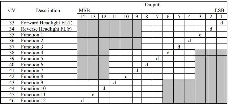
Configuration Variables 33-46 Output Locations
1-14 for Functions 255 FL(f), FL(r), and F1-F12 Contains a matrix indication of which function inputs control which Digital Decoder outputs. This allows the user to customise which outputs are controlled by which input commands. The outputs that Function FL(f) controls are indicated in CV 33, FL (r) in CV34, F1 in CV 35, to F12 in CV46. A value of “1” in each bit location indicates that the function controls that output. This allows a single function to control multiple outputs, or the same output to be controlled by multiple functions. CVs 33-37 control outputs 1-8. CVs 38-42 control outputs 4-11 CVs 43-46 control outputs 7-14. The defaults is that FL (f) controls output 1, FL (r) controls output 2, F1 controls output 3 to F12 controls output 14. The lowest numbered output is in the LSB of the CV, as shown in the table below.
Table 2: Output Position vs. CV (a ‘d’ indicates the default position)
Configuration Variable 47-64: Manufacturer unique
Configuration Variable 65 Kick Start
Specifies the amount of extra Kick that will supplied to the motor when transitioning between stop and the first
speed step.
Configuration Variable 66: Forward Trim
Specifies a scale factor by which a voltage drive level should be multiplied, when the controller is driving the unit in the forward direction. It is interpreted as n/128. If the Forward Trim configuration variable contains a value of "0" then forward trim is not implemented.
Configuration Variables 67-94: Speed Table
The speed table is defined to be 28 bytes wide, consisting of 28 values for forward speeds. A digital controller
that uses this table shall have at least 64 voltage drive levels and can have as many as 256 so that a smooth power curve can be constructed. Note that voltage drive levels are specified in integer values, in the same way as most other parameters. This means that a drive level of 1/4 maximum voltage corresponds to 0100000, not 0010000, as you would expect if the number specified a fraction with a fixed denominator, i.e. value 32 out of a fixed 128 levels (see Definitions section).
Configuration Variable 95: Reverse Trim
Specifies a scale factor by which a voltage drive level should be multiplied, when the controller is driving the unit in reverse. It is interpreted as n/128. If the Reverse Trim configuration variable contains a value of "0" then reverse trim is not implemented.
Configuration Variable 96-104: NMRA Reserved
Configuration Variables 105, 106: User Identification 1 and 2
These CVs are reserved for use by the owner of the decoder to store identification information, e.g. NMRA membership number. CV105 is ID 1 and CV106 is ID 2
Configuration Variable 107-111: NMRA Reserved
CVs107, 108: with CV8=0xEE, a 16-bit manufacturer ID is stored in these two CVs
CVx109-111: with CV7=_____, these three CVs expand the version number feature
Configuration Variable 112-128: Manufacturer unique
Configuration Variable 129-256: Manufacturer unique
CVs in this range are already being used by many manufacturers. Opening up this area officially is an attempt to legitimize what is already being done.
Configuration Variable 257-512: Indexed access area. (see also CV31, 32)
This is the indexed area. It contains a total of 65536 pages, each 256 bytes in length. The first 4096 pages are reserved for NMRA use. The remaining 61440 pages are available to manufacturers for their own purposes. For the manufacturer that needs only 256 additional bytes of CVs, he can simply specify a base address in CV31-32 and not respond if that address is not enabled without actually paging data.
Configuration Variable 880-895 Dynamic CVs
CVs in this range are dynamic and are used for Unsolicited Decoder Initiated Transmission. Manufacturers who utilize these CVs are requested to contact the NMRA DCC WG for current uniform specifications.
Configuration Variable 892 Decoder Load
Specifies the current load of the decoder. The load is volatile and is not stored across power interruptions.
Bits 0-6 indicate the value of the load with 0 indicating no load
Bit 7 indicates a positive or negative load.
Configuration Variable 893 Flags
Up to 8 dynamic flags can be transmitted
Bits 0-7 Reserved for future use.
Configuration Variable 894 Fuel/Coal
Specifies the amount of Fuel/Coal left before the decoder will stop the locomotive. A value of 0 indicates that the Fuel/Coal is totally consumed, a value of 254 indicates totally full and a value of 255 indicates that this CV is not currently supported and its contents should not be transmitted
Configuration Variable 895 Water
Specifies the amount of water left before the decoder will stop the locomotive. A value of 0 indicates that the water is totally consumed, a value of 254 indicates totally full and a value of 255 indicates that this CV is not currently supported and its contents should not be transmitted.
Configuration Variable 896-1024 SUSI (Serial User Standard Interface)
Reserved until March 2005 for use by SUSI to define CVs for Sound and Function auxiliary modules.
Table 3 Accessory Decoder Configuration Variables
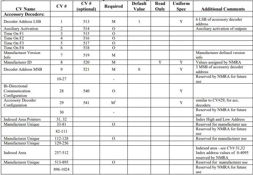
Descriptions of Configuration Variables for Accessory Decoders
Previous version of the NMRA Standard established CVs 513-1024 to be used by accessory decoders. CVs 1-512 were reserved for NMRA use. However, many accessory decoders were sold that used CVs 1-512. This was done for various reasons, including in inability of some command stations to access CVs above 512. In recognition of many accessory decoders using the 345 lower CVs and the desire to create more space for manufacturers, the CV definitions as previously defined have been moved from 513-1024 down to 1-512. Using the CVs 513-1024, as defined in Table 2, are optional. The manufacturer may use these upper CVs in any manner they see appropriate. These changes will allow existing accessory decoders to use CVs 513-1024 as previously defined.
Configuration Variable 1 [513] Decoder Address (LSB)
Contains the low-order address bits for Accessory Decoders. The high-order address bits are stored in CV9 [521]. Two types of Accessory Decoder addressing are supported: Decoder-Address and Output-Address. An accessory decoder must support one type, and optionally the other type. The type of decoder is specified in CV29 [541], bit 6. Decoders using either type of addressing will respond to the same Accessory Decoder Control Packet when CV1 [513] = 1 and CV9 [521] = 0. The factory default value is 1. The type(s) of addressing supported must be clearly documented in the manual and on the packaging.
(1) Decoder-Address: Contains the six least significant bits of the accessory decoder's address in bits 0-5. These bits are transmitted as bits 0-5 in the first byte of the accessory decoder packet.
(2) Output-Address: The user places the output address Contains the address value results from the following formula: Output Address modulus 256. (ex. Output Address mod 256, or Output Address % 256). The values contained in CV1 [513] and CV9 [521] correspond to the bits in the Accessory Decoder packets as follows:
Accessory-Output = (CV1 [513] + (CV9 [521] *256)) - 1
Bits 0 & 1 of the Accessory-Output are transmitted as bits 1 & 2 of byte 2 of both Accessory Decoder Control Packets.
Bits 2-7 of the Accessory-Output are transmitted as bits 0-5 of byte 1 of both Accessory Decoder Control Packets. The three least-significant bits of CV9 [521] contain the ones-complement of bits 4-6 of both Accessory Decoder Control Packets . If an accessory decoder supports more than one sequential output the value in CV1 [513] will be the first output in the series
Configuration Variable 2 [514] Auxiliary Activation Bits 1-8 = Auxiliary activation: = "0" output is not activated by an auxiliary input, "1" output can be activated by an auxiliary input.
Configuration Variables 3-6 [515-518] Time On for Functions F1-F4
Functions F1-F4 can have the time the outputs are active set by Configuration Variables 3 [515] – 6 [518]. Configuration Variable 3 [515] controls Function F1 and Configuration Variable 6 [518] Controls Function F4. Contains a time that the output is on each time the state of the function is activated. A value of all "0"s indicates continuous on.
Configuration Variable 7 [519] Manufacturer Version Number
See CV7 for the description.
Configuration Variable 8 [520] Manufacturer ID (See list of Manufacturer IDs)
See CV8 for the description.
Configuration Variable 9 [521] Decoder Address (MSB)
Contains the high-order address bits for Accessory Decoders. The low-order address bits are stored in CV1
[513]. Two types of Accessory Decoder addressing are supported: Decoder-Address and Output-Address. An
accessory decoder must support one type, and optionally the other type. The type of decoder is specified in
CV29 [541], bit 6. Decoders using either type of addressing will respond to the same Accessory Decoder
Control Packet when CV1 [513] = 1 and CV9 [521] = 0. The type(s) of addressing supported must be clearly
documented in the manual and on the packaging. The bits transmitted are the ones complement of the value in
this CV.
(1) Decoder-Address: Contains the three most significant bits of the accessory decoder’s address in bits 0-2. These bits are transmitted as bits 4-6 in the second byte of the accessory decoder packet.
(2) Output-Address: Contains the address value results from the quotient of the following formula: Output Address divided by 256 (Output Address div 256, Output Address / 256). See CV513 [1] for an explanation of how to determine the contents of CV1 [513] and CV9 [521].
Configuration Variable 28 [540] Bi-Directional Communication Configuration
Used to configure decoder’s Bi-Directional communication characteristics. when CV29 [541]-Bit 3 is set
Bit 0 = Enable/Disable Unsolicited Decoder Initiated Transmission
“0” = Disabled; “1” = EnabledBit 1 = Not Used
Bits 2-5 = Reserved for future use.
Bits 6-7 = Flag Bits, Reserved for future use
*Note If the decoder does not support a feature contained in this table, it will not allow the corresponding bit to be
set improperly (i.e. the bit should always contain its default value).
Configuration Variable 29 [541] Accessory Decoder Configurations Supported
Bits 0-2 = Reserved for future use.
Bit 3 = Bi-Directional Communications: "0" = Bi-Directional Communications disabled, "1" = Bi-Directional Communications enabled.
Bit 4 = Reserved for future use.
Bit 5 = Decoder Type: ‘0’ = Basic Accessory Decoder; ‘1’ = Extended Accessory Decoder
Bit 6 = Addressing Method: ‘0’= Decoder Address method; ‘1’ = Output Address method
Bit 7 = Accessory Decoder: = "0" Multifunction Decoder (See CV-29 for description of bit Assignments for bits 0-6), "1" = Accessory Decoder. If bit 7 = 1, then the decoder may ignore the two most-significant bits of the CV number in Service Mode only. Using this feature CV513 becomes CV1, etc. Decoders which perform the translation must clearly document the feature in their manual.
Note: If the decoder does not support a feature contained in this table, it must not allow the corresponding bit to be
set improperly (i.e. the bit should always contain its default value).
Configuration Variable 31 Index Address High Byte
Configuration Variable 32 Index Address Low Byte
The Indexed Address is the address of the indexed CV page when the decoder is set up for indexed CV operation. CV31 contains the most significant bits of the two byte address and may have any value between 00010000 and 11111111 inclusive. Values of 00000000 through 00001111 are reserved by the NMRA for future use. (4096 indexed pages) CV32 contains the least significant bits of the index address and may contain any value. This gives a total of 61,440 indexed pages, each with 256 bytes of CV data available to manufacturers.
Manufacturer ID codes as assigned by the NMRA
Power Source Conversion codes as assigned by the NMRA
The following Power Source Conversion codes have been assigned by the NMRA Technical Department.
Manufacturers wishing to use conversions not on this list can apply to the NMRA Technical Department for
the assignment for a conversion ID.
00000001 = Analog Power Conversion
00000010 = Radio
00000100 = Zero-1
00001000 = TRIX
00010000 = CTC 16 / Railcommand
00100000 = FMZ (Fleischmann)